Paul
as collected and (very little) formatted by addie walti
The start of a thread is marked with 0-
"wrong file type" !?
Scenery 'movement'
importing objects
Just a thought on CMD 112
Scenery 'movement' (part 2)
Suggestion on the TE !
Detroit street circuit little bug
help please!!:)
cc-line (cmd112+"t/w")
CC-Line (max number)
Underlay bitmap
Fuel supply
Help needed with JAM Editor
CC-Line Idea
unk hunters report (0xd4 and 0xd6 baged)
0-Ando from 195.94.90.25:
Hi all,
I have a strange problem with my current track: when
loading the track in GP2, it says it is a 'wrong file
type'! An older version (only a few days older) still
works, and I can't remember having changed anything
else than the textures for some objects and some
slight changes to the shapes. I also changed the JAM
files, but this shouldn't cause the track not to load,
should it?
Did anyone experience similar problems? It would be
really cool if someone could help me. I will also look
into this again and will report my results.
many thanks!
ando.
gp2@webfactory.de
SNQQPY.Dog from 194.168.68.179:
Hi Ando
Have you been adding objects etc?? this usually occurs after you have been inserting
too many cmds?
Try reducing the number (any not needed)that might help...hope so anyway ;o)
Cheers
David
Robinio from 193.172.232.88:
Sorry Ando, I'm finally replying to the correct message.
I've had this problem too sometimes, but I only had it when I changed something in
the track with a Hex editor. Did you change anything with a Hex editor by any chance??
This is the only thing I can think of at the moment wich may be causing your problem.
Regards,
Robinio
Ando from 195.94.90.25:
thanks for the reply, but unfotunately I didn't add any cmds! I have 617 trk cmds
in both the working and the bad file. I
haven't added pit cmds either. :(
and I think 617 cmds shouldn't be the limit!? I already have removed all the cmds
which aren't necessary at the very
beginning.
anyway, thanks for your help.
ando.
gp2@webfactory.de
Ando from 195.94.90.25:
I didn't change anything with a hex-editor. I only used the TE and the JE! Not even
the OE!
anyway, thanx for your reply.
ando.
gp2@webfactory.de
Ando from 195.94.90.25:
FIXED
hi all,
I have fixed the problem. It was simply that I added one Internal Object. Seems like
it was one too much. :)
I hope I can still add cmds though...
cu
ando.
gp2@webfactory.de
SNQQPY.Dog from 194.168.65.83:
Hi Ando
Glad to hear you fixed it...objects eh? I wonder where I heard that one before?
:o)
Let us all know if the cmd number is still a problem and if so what it fails at?
Cheers
David
Ando from 195.94.90.25:
the number of cmds doesn't seem to be a problem yet. I have inserted several 0x80
cmds and the track works as usual. But when inserting another int. object the track
doesn't load anymore. I currently have internal objects up to ID 71, #72 would crash
the track.
now for Bob P and his TE bugfix summary:
My problem is that I still need many int. objects! So I tried the remove int. object
function which shouldn't change the IDs o all the other int. objects, but it does!
When removing say ID #30, it removes it and there are only ID #29 and then ID #31.
30 is gone and all the ones following it still have their old ID.
that's what it should be like. but when updating the view (F5), the int. object with
ID #31 has ID #30 and all the ones following have another ID (-1), so I would have
to change all the object descriptions.
It would be cool if it was possible to remove int. objects without having to change
all the object descriptions. I hope I was clear enough, otherwise please tell me
and I will try to explain it once again.
cu
ando.
gp2@webfactory.de
John Verheijen from 195.121.26.51:
you can replace the Internal Objects.
So the other Internal Object still keep the original ID's.
Just click with the right mouse button on the Internal Object and choose Replace
Internal Object.
Hope this solve your problems.
John Verheijen
Ando from 195.94.90.25:
hi,
thanks for the tip! I never tried this function. :)
But as I just realized that the whole object part in my track has to be tidied up,
I just removed all the int objects that aren't necessary. Now I want to remove the
object descriptions that I don't need, but this doesn't seem to work. When right-clicking
on one of them, I get the same window as if I clicked on a track cmd. I tried 'Remove
Track Command', but the TE crashed everytime. :(
Is there a way to remove the object descriptions?
many thanks!
cu
ando.
gp2@webfactory.de
John Verheijen from 195.121.26.52:
Why remove the Object Definitions???
just change the ID1 of the object definition.
just fill in the values you need and you have a new Object definition.
Or if you don't need another object definition try ctrl+x to delete the object.
John Verheijen
0-Robinio said the following:
Hello folks,
It's me (again...)
Although I fiddled about with the scenery on that particular corner (thanks for the
advice guys!), the scenery 'movement' never seemed to go away. It got better (most
of it is gone), but it's not perfect yet.
Here's what I did up to now:
I inserted a 'scenery adjust left' command and another 0*b8 command. This didn't
help a lot, untill I inserted a 'bridge scenery' command, with args of 4. With this
command it cleared up a bit but the tree line is still moving a little bit up and
down (or back and forth; I can't really tell).
Rite, does someone have a suggestion (again)?
Best wishes,
Robin
Sjon from 62.216.0.139:
You moved the scenery back to 7000 not? Try moving it closer to the track, 2000 or
so. I have no idea or it will help, I am just speculating here..
It could be 7000 is to high. Try building the scenery "on scale". for instance:
instead of using the large tree line in t_monsp1.jam, t_monsp2.jam and t_monless.jam
use the trees from t_monsp3.jam, this one contains a smaller tree line. With using
a texture from t_monsp3.jam you can use a value like 2000 in your 0xb8 command and
get the same effect as using a texture from t_monsp1.jam and 7000 in the 0xb8 command.
addie from 194.191.82.13:
hmm
i dont know the z-values you used in the 0xb8 cmds. but maybe there are certain values
that fit better to the game than others (e.g. 2048 instead of 2000; things like this).
maybe you could check the original tracks and copy appropriate values from there
...
are there gradient changes in the mentioned section ? if yes, maybe breaking the
existing track sections in smaller parts and inserting more 0xaf-0xb8 pairs could
help ...
just my few cents
addie
Paul Hoad from 194.222.192.203:
It's just an idea I have no idea if it will work but how about using a height or
distance form the track that is more of a computer number say
256
512
1024
2048
4096
8192
16384
32768
65535
etc....
perhaps if there is division going on rounding errors might be making some problems,
numbers that are divisable by 10 may not always be the best try a number that is
divisible by 16
just an idea
Paul Hoad
Robinio said the following:
Regarding your message Sjon: I've had my scenery as close as 3000. But I'll try 2000
or even 1000. Hey, maybe I'll get lucky once! (I hope).
I'll also try Paul's advice: change the numbers so they're devidable by 16. (Thanks
Paul).
Regards,
Robinio
0-Andrew D said the following:
I was wondering if anybody has tried to link it to the action the cars sometimes
take underbraking for corners.
Keyboard players esspecially, if you notice when you are behind a cc car and you
brake hard into a corner, how the car suddenly steps out and spins sometimes. I know
that the cmd is after the corner, but could it be linked. I haen't had enough time
to check this out, but if anyone has tried in the past, could you let me know
AD
Ripping said the following:
Along the lines of what you are talking about, I noticed while I was running a Monaco
race (original track) that in Rascasse (last corner) if you are very close behind
a CC car going into this corner GP2 will put you on the outside of the CC car and
inevitibly into the wall (Steering help on).
This seems a case of the CMD 112 affecting the human car and not the CC car.
I assume rascasse has a 112 cmd?
cheers
Ripping.
Andrew D said the following:
I checked that out, and it seems that the ony places at Monaco that have the 112
cmd are Ste Devote, Casino Sqr. Mirabeau and Portier. I could be wrong
AD
addie from 194.191.82.13:
my idea of the cmd 112: its simply two radius, parabola. if you compare the additional
arguments to the regular radius arguments, it looks obvious. but i had not tested
it up to now.
(i guess that was already mentioned before in the forum)
0- Robinio said the following:
Hello folks
Just a quick question here regarding the scenery.
I'm busy with a track now and I'm also doing the scenery. Normally I only have small problems wich can be solved easily, but now I've stumbled across a problem wich has driven me completly potty...
I've inserted a tree line (with a scenery command 0*b8 and a 0*af infront of that) on the left hand side of a sharp right corner. The 0*af command arg's are '-16384' and '16384' (in that order). In the args of the 0*b8 I've made sure the scenery starts well clear of the track (I've had it up to 7000!)
When I'm racing and approaching this corner the scenery kind of 'moves' back and forth and changes size a bit. Really strange. Does it have to do with the rotation of the bitmap on the ribbon, or am I completely looking in the wrong direction??
Thanks in advance, Robinio
Michaël 'NRG' Hompus from 195.241.140.22:
You mean the scenery comes to the track, while it should be further away?
Well, we (DET) had the same problem with the chicane of the Nurgurgring '98, when
setting the width of the 'scenery' at -16348 and 16348. The solution is to make this
smaller, maybe 10000.
Greetinx Michaël 'NRG' Hompus
Sjon Stigter from 195.64.69.141:
Hi,
Robinio, I don't know what's causing your problem but I just wanted to correct the
thing Michael said. The reason the scenery wend nuts at the Nurburgring was because
I used values of -20348 and 20348 at the 0xaf command. This value worked good at
straights and even worked fantastic on outside turns (it corrected the texture so
it became less stretched). But on inside turns it went silly and came across the
track. Sorry I cannot help you but I just wanted to correct Michael so you wouldn't
be looking into the wrong direction :)
Regards,
Sjon (DET)
Bob P said the following:
I had a similar problem with a track I am working on;
I solved it by adding a second (or more depending on track section length) set of
scenery commands. Use the first parameter of the 0xaf, the offset (if your corner
is say, ten units long, make this 5). Put the second 0xaf after the first ribbon
structure command, then put the next ribbon structure command.
I'm no scenery expert, but I think this will solve your trouble.
Bob P
Mal Ross said the following:
Further to what Bob said, you could alternatively use extra 0xC0 commands to define the scenery on the left side (the outside)
of the corner instead of the extra 0xAF commands. This way, the inside of the corner won't be affected by the changes.
Mal.
addie said the following:
maybe in addition to multiple scenery-cmd-pairs the cmd 0xba shortcut scenery could help ?! for details see chapter 3.5 of the scenery tutorial of martijn keizer.
in any case, be sure to have adapted the number of repetitions in the texture mapper cmd (a5 in 0xbc) for that area. if a texture area is streched like at the outside of the corner, it sometimes is necessary to increase this number.
i hope it helps
addie
Martijn from 130.161.124.18:
IF you have an exact parralell line of trees along the track, (that means the a2-a6
of 0xb8 and the 0xAF are EXACTLY the same, AND the trees still seem to come closer
and further from the track, please check whether there is a "trackwidth change
command". I *think* these cmd affect not only the trackwidth, but the overall
perpendicular scale of the track (I KNOW distance to fences also changes because
of trackwidthchange, but I'm not sure about scenery).
Martijn
Robinio from 193.172.232.88:
Regarding your message Sjon: I've had my scenery as
close as 3000. But I'll try 2000 or even 1000. Hey, maybe
I'll get lucky once! (I hope).
I'll also try Paul's advice: change the numbers so they're
devidable by 16. (Thanks Paul).
Regards,
Robinio
0- yunisaz said the following:
Hi
can any help me with import/export of objects?
What I want to do is import all the objects from track A to track B, with all its x,y positions as they are on the origional track...how do I do this?
The method I tried is to cut from the object view table and then paste on to the new track object view table, but the message i get is clip board is empty,
I`ve also tried exporting table data to a csv file, but have problems importing
to the data on to the new track.
I might be doing this all wrong, so can any one point me in the right direction?
thanks
yunisaz
Fat Rat from 24.113.17.7:
No problem .
#1 You have to do 1 object at a time(Saved GPO file) nothing do with any tables
.
In the tree you highlight the internal object , then right click . choose export
& save the gpo file .
Now you also have to go through that object to find all the texture ID# that object
uses .
#2 you have to find the object definition & write down all of those values.
Then goto the new track , in the Object menus . Choose insert new internal object
. then open the gpo file you saved , and it will be given the object # at the bottom
of the list .
Now you must save the track , Now create a new object definition , again it will
be the # at the bottom of the list choose the ID# of your imported GPO file , then
the values you wrote down from the other track .
Save the track again .
Now you have to assign the jams with the right texture ID's , sometimes it's only
1 jam , other times it maybe 4 or 5 jams .
Now again save the track .
Last but not least . now use your new object definition ID into a track or pit section .
If the object definition is the same as the old one ( except for the internal object # ) this object should appear the same distances from center & height Etc. as in the old track .
Now remember that was only 1 object
Hope this helped
CU Les
Martijn from 195.109.165.2:
you forgot to emphasize this procedure will sometimes/often crash the track completely, so be sure to have a zillion backups around.
Also sometimes the track just won't accept any additional objects after a certain point. :-( And, to make matters even harder, it seems you cannot export an altered object, but only an original one. Not sure about the last one, though.
Fat Rat from 24.113.17.7:
Re your last point ( altered objects)
I have had no problems in this area . though I have run into problems importing identical(UnAltered)objects back into it's native track (Duplicates)
Seems to work better if I alter the object slightly ( which makes it an unknowm object ) then save it , import it .
GP2 seem to wonder why you would want 2 indentical objects in the same track , so if one object is altered this seems to be more acceptable to GP2.
Thanx Les
MartIJn from 195.109.165.2:
Hey, That could be it!
I just exported an object and inserted it again, then tested if the track still worked (which it did not). I planned to make changes later, obviously.
I guess GP2 might indeed object (to make matters complicated :-) to two identical internal objects. Therefore change first, test later.
=======================
By the way, there is another thing concerning texturing objects, that I want to throw in the air.
1) I think that there's a code somewhere in the object-texturing section that sets the light-level of an object. Remember the starting-marshall from TunnelTrack? The flag seems to be a lot lighter than the marshall itself (which is another object). Maybe the starting light is set to be always brightest level (like the "light ribbons cmd")
2) Textures on non-square planes of objects can have two ttexturing modes: First is that the normal texture-shape is preserved, but the sides
of the texture that falls outside is cut-off. (like the grandstand-sides, I always wondered why there is no red part like in the JAMfile). Second is that the texture is distorted so that the square texture fits on the triangle plane.
This difference is very apparent on the different types of houses on the aforementioned TunnelTrack, where you can see this on the little triangle walls near the roof.
Martijn
Paul Hoad from 194.222.192.203:
I often suspected that some part of the object might point to an overal id for that object (perhaps the section WORD) you might like to try editing the gpo file with a text area so that this is different from the second object.
just a thought
Paul Hoad
Suggestion on the TE !
0-Daniel Ramos from 129.24.14.49:
Hi,
I think it would be nice to have in the object window
(that one we access when seeing a tree for example
and clicking on 'edit') a preview of the ADVERT
that will appear in the game.
let me try to be more specific in case I am not
being understood.
so far, we can see a preview of the bitmap
of a tree, but we can't see a preview of the
bitmap of an advert or side advert.
that would speed up a lot of people's work , at
least it would help me to make tracks faster.
and finally , the preview has to be exactly
what we are going to see on the track ( so
if ,in the object window, we switch the angle
making the advert show its back, therefore the new
bitmap will be shown) so we can have an idea
of which advert (campari, shell, ect) we can use
in ceratin parts of the track.
hope I was clear, although I don't have this feeling.
Paul, if you need me to be clarify that, let me know.
Regards,
Daniel
John Verheijen from 195.121.26.79:
you can see the object in the internal object definition tree.
just click with your right mouse button on the object you want to see and choose
3D view.
then you see the object with the right textures.
Bob Culver from 153.35.201.8:
But it would be faster if it popped up when you were selecting objects in the placement
mode. It seems that an
enhancement like this might be simple for Paul to create.
Daniel Ramos from 129.24.14.106:
Hi,
My point was to see the object (advert) texture
in the object (or object definition) window in
a section tree. Why? because it is faster.
more convinient(is this speeled right?)
With the 3d view in the IOD tree, I can
only see the object lines(shape). even if I could see the
texture, still would be better to have a preview
in the object offset dialog window(Sorry for
too many names for the same thing :-)
regards,
Daniel
Daniel Ramos from 129.24.11.39:
(Paul, please read)
Hi,
Bob Culver got the message. That is exactly what I was thinking of.
Thanks Bob. and like you said , (to Paul) this seems to be easy addition to the TE...so
why not make this update...
:-)
Thanks,
Daniel
Mal Ross from 193.237.112.166:
Rather than pressuring Paul into responding, can all suggestions such as this one
be sent to Bob P by email for the time being. Bob will then gather all comments together
and Paul will be able to decide upon action to take then. :)
Cheers,
Mal.
Bob P from 24.64.2.36:
I was going to say that... although I did make note of all the comments, and stored
them with your mail...
So remember folks, for the next few weeks, while thinking of what you would like
from a future version of GP2 TE, write to me. I will not actually respond, rather
I will summarize what people have to say and "report" to Paul Hoad.
A bit of "market research" you might call it :)
Bob P
bobjoycana@home.com
address mail for this with subject GP2 or GP2 TE...
0-fabrice lagardere from 152.163.207.62:
Creating detroit street circuit 84/89, layout and ccline are ok now.
For pits, i just have a small bug: a strange green texture just at pits entry on
each verge (not on the road, so this is not a problem with scenery which i remove
to "0"). Every cmd seems ok though, i don't understand. Does anybody have
an idea?
Thanks for your help
Andrew D from 210.8.232.3:
It could be a texture on the surface, or the view into the pits could be wrong.
I am not really sure, but if you go through Addie's pit tutorial step by step, that
should help
AD
addie from 194.191.82.13:
i'm afraid the pitlane tutorial wont help you here.
snqqpy.dog once helped me with a similar problem in the bremgarten track. the cmd
0xaf in the appropriate track section was set to 16384 (for rightside pits) and he
set it to 24345 (o.s.s; see the bremgarten track for the exact value). this solved
the problem, although we didnt understood why :)
maybe it helps
addie
0-addie said the following:
hello
cmd 112
its probably not news. i made my tests with the cmd 112 cc-line sectors and came
to the conclusion, that the two 0x70-only-unks really are the 2nd radius. the regular
radius arguments describe the radius at the beginning of the sector. the radius as
given by the two unks describe the radius AT THE END of the sector. the line between
beginning and end of sector has a transition radius, similar to a sector of an ellipse.
if watching the originaltracks and imagine the parabolas at the appropriate sectors,
it becomes obvious. a very good example is f1ct16.dat, adelaide.
another proove of this is to set the regular radius in a cmd112 cc-line sector
to 0 (straight) and also set the two unks to zero: you guessed it, it becomes a straight
sector. i checked that.
last but not least: to transform a cmd112-sector to a regular cmd80 sector, just
copy the values of the regular radius to the two unks. theoretically. practically,
it doesnt work. the second radius seems to have to be bigger about 1000 than the
regular radius (smaller 1000 if turning to the left), else the cc-line get messed
up. thats what i found in the few tests i did here.
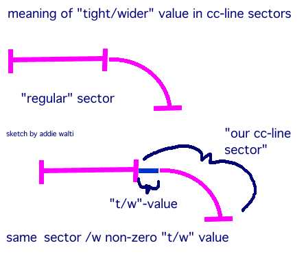
tighter/wider - argument
as you may know, the length unit of a cc-line sector is the same as with the track-sector,
16 feet, 4.87m. some of you may have had problems with this big grid when developping
a reasonable cc-line. so did i. i always wondered why we have to deal with such a
large unit here. the answer ? we dont have to actually ! we can be as precise as
we wish, because we have the tighter/wider - argument !
maybe we should call it offset-argument. my tests didnt allow me to come to a detailed
conclusion, but as far as i saw, values between about +/- 300 do SHIFT the COMPLETE
cc-line sector within +/- 1 length-unit ! bigger figures start to give strange and
stranger results. in original tracks we see a range of maybe 9 to 288 as a value
of this argument. (but i checked negative values also, and they work in the expected
way.)
i didnt test this argument with cmd112 sectors, nore with straights, but i guess
it also works here.
and, these two ideas also partly explain some strange things in the TE when showing
the cc-line in the track-view. the first becomes especially obvious in original-adelaide.
the 2nd is much more subtle.
happy cc-line editing
addie
Paul Hoad from 194.222.192.203:
Then perhaps this tighter wider value should somehow be added to the length value
before the calculations are made, this might explain why a corner seems to go round
much too far sometimes....
so if we can determine the units I'll be happy to try it out in the editor
length = length + (somescale*)(unks)
we would need to deremine somescale as of course length is in 16 feet units what
is unks in?
Paul Hoad
Paul Hoad said the following:
What is the largest +ve and -ve number anyone has every seen for this tighter/wider
value I have 242 at estoril
Paul Hoad
addie from 194.191.82.13:
i looked at every original track: the largest value i found was 288 but i forgot
where :) and no negatives.
as far as i saw the shift is always STRAIGHT. that means, the angle at the exit of
the cc-line sector remains the same. if you give a positive value, its like inserting
a little straight before the sector. if you give a negative value, its like cutting
a bit off of the previous sector.
first i thought about 1 length unit = 256 "tighter/wider" units, but then
a value 255 doesnt make sense. and there are a few values 255 in the original tracks.
so maybe its 1 length unit = 512 "t/w" units ? (i dont know very good the
english length system, so there is maybe a unit that makes more sense)
on the other hand, values about 500 already start to give strange results ...
addie
Paul Hoad from 194.222.192.203:
well this value is a WORD so it could be 0 - 65535 but it sounds like its not being
used that large ever....
Paul Hoad
Michaël 'NRG' Hompus from 195.241.140.109:
Hi, I found the tighter/wider options, so I want to explain somethings I saw:
as Addie said:
values about 500 already start to give strange results
this is because when the cc-line hits the side of the drivable sector (between the
walls), so when the cc- line hits the wall, the cc-line comes back with the degree
(I hope this is good English)
For example, when the cc-line goes off-road to the wall with a degree of 45, then
it will come out of the wall also 45 degrees but now the other way (mirror) and so
when it comes at the other side at the wall it will again mirror to 45 degrees the
other way.
Off course the cc-line is not a straight line, so that's why you get those strange
effects, but if you want to test, take a straight pice of track, with the walls very
close to the road (banks:2) then be sure the cc-line doesn't hit the wall before
this straight section, then make the cc-line hit the wall at the begin of the straight
section, end then it will become to cross the road, till there is a turn or a cc-cmd.
as Addie said: (again)
values about 500 already start to give strange results
This is because at that section, or: the cc-line hits the wall (and mirror's). or:
because you make the cc-line, by making it longer, so wider, take a turn of more
then 90 degrees.
Maybe 512=90 degrees because a turn of 80 degrees also hit the wall it could be that
that's why the cc-line already act strange below 500.
I think you have to count this value as an extra radius so having a radius of 10
degrees, plus counting the thighter/wider of 512as90 degrees, it would be:
10+90=100 degrees, and a very strange acting cc-line :-)
I hope you can make something about my point.
Greetinx Michaël 'NRG' Hompus
addie from 194.191.82.13:
whatever figure +/- 300 you enter as t/w-value in a cmd80 cc-line sector, it DOES
NOT change the angle at the exit of the sector. (btw: i made my tests in the 2nd
chicane of hungaroring, around 2nd split. there you have a cc-line sector with a
t/w value of 259, and enough verge-space. but first you have to neutralize the
following cmd112 sector by setting the radius and the unks to zero).
so the t/w-value seems to be a simple straight offset of the BEGINNING of sector.
(i wonder why t/w-value should be an add-on to the regular radius ?! if you want
to increase the radius then you could do that by increasing its value. precise enough.)
and: with t/w-values greater than say 1000 the cc-line-sector goes crazy even WITHOUT
touching the fence.
addie
Paul Hoad from 194.222.192.203:
I'm getting confused here... perhaps some clarity....
What are we trying to say.
a) The unknowns of the cc line affects the cc line (simple enough!)
b) Previously we determined that these values effect the "sharpness" or
a corner.
c) Now Addie is sharing his opinion. about what this does..
d) I have a number of questions arising from what you've seen addie.
If I take a 90 degree corner and put a value of say 100 in the unk what effect does
this have on the corner? do I go round more or less that 90 degrees
now
If I take a 90 degree corner and put a value of say 200 in the unk what effect does
this have on the corner? do I go round more or less that 90 degrees?
As I understood what you where saying is that becuase length is in 16 feet units
sometime this is not accurate enough for the length of a section (forget radius for
the time being!)
so Addie is suggesting (I think?) that the unks? could be a value that is added to
the length to effect the calculations once the radius is fixed! this will have an
effect on the corner! so if I'm correct then you would expect for the value of the
unk to be some fraction of 16 ft hence there must be some scaling value on this unk
to get it into some fractions of a single track length (16ft)
ok! I think this is where we are. If anyone else can shed any light on this value
I'd be happy to try it out in the editor
addie said the following:
-if you take a cc-line sector with a 90degree corner and put a value of 100 in the
unk, the corner is still a 90 degree corner, but starts a little further. by inserting
a value 100, you insert a little straight BEFORE the beginning of the mentioned corner.
i dont know HOW LITTLE the piece of cc-line is in detail, but i guess, some 500 will
equals one cc-line length unit ?! but as i mentioned before, i havent done many tests.
(thediscovering of how the cmd112 cc-line sectors work is much more important to
me. btw: yesterday i succesfully included the first of these parabolica-cc-line sectors
in the cc-line of my actual track. it worked absolutely as expected)
-if you insert a value 200, the OFFSET of the beginning of the corner is shifted
double the distance.
-thats right, a length unit of 16 feet does not let you be as precise as you wish
to be sometimes.
-now we were only talking about the tight/wider unk. and the functionality of the
cmd112 unks, could that be included in the TE ? that would be very useful. (but im
afraid that could be a complicated one to implement ?!)
addie
addie said the following:
ehm, sorry
-just to be sure you get me right here. you insert the value 100 to the "tighter/wider"
value...
(the unks of the cmd112 are a different story...)
addie from 194.191.82.13:
in the meantime i found: it was timmo (i'm sorry, i dont have the e-mail address
anymore) in august who brought up the cmd112 cc-line sectors being sectors with transition
radius in the forum.
here is what timmo posted (i hope you dont mind seeing it again, timmo?)
timmo said the following:
Summary of theory...
CMD 80 (0x50) describes a circular curve (constant radius)
CMD 112 (0x80) describes a transition curve (variable radius).
the first radius (like in cmd80) is the radius of the first subsection of the sector
the second radius ( displayed in the 0x70 only boxes ) is the radius of the last
subsection of the sector.
Change of radius for each subsection is (endRadius - startRadius) / (Length -1)
Details...
Looking at the Hungororing (f1ct10), you may notice
1: CMD 112 (0x70) generally follows a CMD 80 (0x50)
2: The graphic of the CCLine is (pretty much) OK until the first CMD 112
now look at the CMD 112's a little more closely. It occurred to me that if the CMD
80's describe a circular curve (constant radius), maybe the CMD 112 is a different
type... In fact, maybe the CMD 112 is a 'Transition' curve, with a start radius given
a 'Radius', and an ending radius given by the 'Direction 0x70 only' parameters.
For example, the first hairpin has the following CCline
Index 3 Length 21 Radius 12630
Index 4 Length 23 Radius 12630 0x70 only? params are (sign/Scale) 0 and (radius)
15700
So maybe CCline index 4 starts with a radius of 12630, and transitions to a final
radius of 15700, with each subsection having a slightly different radius
startRadius = 12630;
for each subsection from 0 to 22 do
{
Radius = startRadius + subsection*(15.700-12.630)/22;
theta = theta + 1/Radius; // direction
}
Then each subsection can be treated as a circular curve. Maybe this is accurate enough?
maybe not?
So I broke the cmd112's into lots of cmd80's, each length 1, each with a slightly
different radius calculated from the above formula
The resulting display in the TE is very encouraging
Problems
1: the CCline still deviates from the track, but notice there is still one more unk
for both cmd80 and cmd112, an it does seem associated with the remaining deviation.
Maybe its a fixup?
2: What exactly is the sign/scale relationship with radius and 'Radius Scale' in
TE
I came up with: realRadius = signScale * 65535 + Radius ?
This gives me values very close to those in TE, with exception of original CC sector
14 where radius is 21144 and signScale is -4 , I calculate 240996, TE has 306535,
a difference of 65539?
NB: I couldn't get a value of 240996 entered into TE's Radius Scale box (is this
a bug?, or my wrong assumption?)
3: I only looked at f1ct10. I think it should not take very long to change the TE
so it draws the cmd112's using this idea.
4: TE suggestion. The Offset to CCline Data info is missing from the Track Offsets
treeview
Other ideas ...
This structure would support a CC car 'look ahead' idea.
If we put a CMD 112 going INTO a bend, will they brake later?
I also guess that CCLine UNK3 and UNK4 could be a sign/Scale and radius.
Check gp2.com/cc-line/ccunk.htm
Monaco is a right hander (2,34576),
Jerez a Left hander (-9!,55360)
I will send the mod'd f1ct10.dat to Auke Haarsma and Paul Hoad.
Maybe Auke, you can post an image, or the file? at gp2.com?
Paul_Hoad from 194.222.192.203:
Well, your right addie this might be difficult to add in to see what addie means
goto to
http://grandprix2.ga-sports.com/trackedit/cc_sect.JPG
Paul
addie from 194.191.82.13:
for implementing the cmd112 cc-line sectors. maybe you could take the approach of
timmo (see the other posting) and divide the sector into pieces (maybe half length
units) with different, but constant radius ?! it would not be perfect, but it would
be a big advantage to the actual solution ?!
addie
0-laurent said the following:
Is one limited in the number of cc-line?
addie from 194.191.82.13:
yes
especially for curved cc-line sectors !
i dont remember the exact number, but you have to sum the curved cc-line sectors
and the curved pit lane sectors (no joke!), and the number should not be greater
than about 70 (?) the max number of cc-line sectors (curved+straight) is probably
at 256 (?)
addie
Index
0-Bob P said the following:
I am just wondering if there is a specific bitmap size that one should use? I want
to put a trackmap as the bitmap (what else?)... I load the bitmap, but nothing comes
up.
Is it a size thing, number of colours thing?
Bob P
Paul Hoad from 194.222.192.203:
There might be a number of colors thing I'd go for about 256 colors if I were
you I'm not 100% sure though.
you have to have the bitmap button down that the one to the right of the world looks
like two circuits
now to move and size the image goto misc config in the tree
by double clickin on the UnderLayBitmapX etc you can move the image around. the size
of the image is upto you the track editor will stretch it to fit what you tell it
to in the width and height section.
if it doesn't show up try another bmp format!
my backdrop image which is 450x525 and 24 bits perpixel bmp certainly works
Paul Hoad
David Richards from 202.0.75.16:
I wondered about this too, until Ando told me what to do. At the bottom of the track
tree, you see misc.config. go there and you see entries for width,height and x,y
position. Double click on these and adjust them until they meet with your needs.
Good luck
0-Klee Dobra said the following:
A question to all editors,
Is there a way, once a new track has been created, to make an alteration inside the
edit project?
Here is the problem: Several of the new tracks, when race length is altered with
gp2edit to say 25% or 39%, will not provide enough fuel for the cc cars to finish;
and, when they pit for fuel late in the race, something goes wrong and they all retire.
If the amount of fuel could be increased this would not happen. Or, perhaps there
is another solution that I've not considered.
Thanks in advance for your help.
Klee Dobra
Ian Hill said the following:
If you have Track Editor you can change the fuel load by loading the track file and
editing the "CC Setup" dialog box. The box includes a "Fuel Load"
box and also a button to calculate the approximate correct amount of fuel for a lap.
I don't know how this works so it may not be accurate for some extreme tracks eg
flat-out ovals etc. Just increase this number if the cars use all their fuel too
soon.
BTW The reason cars retire even after they pit is because the GP2 program thinks
they should have the right amount of fuel on board given their pit strategy, so just
changes the wheels. This is probably because the programmers did not expect new tracks
to be built and knew the fuel load was accurate on the 16 original tracks.
Hope this helps.
Regards
Ian Hill
Filou said the following:
Hi !
In TrackEditor, go to Pit Stop Strategy in the Pitlane menu, and put in the number
of laps you've put in GP2Edit. Then adjust the pit stops. This will affect the CC
Cars Pit stops. Then you must try to increase the amount of Fuel in the CC Cars Setup
section in the Edit menu. As you have increased number of laps, you will have to
use "Trial and error".
Filou
Klee Dobra from 209.86.19.69:
Hay Ian & Filou...
Thanks for the assistance, I'm off to give them a try-I'll let you know!
BTW. Ian, glad you have someone working on your banked Monza. It's a great track.
You did a great job getting it put together, I hope those adjusting it can make it
as realistic as possible.
Thanks again,
K.D.
0-Filou said the following:
Hi !
Working on my track (a realistic Melbourne 98 on which I have already spend some
months without any success ... what track editing is difficult for normal people
! :-), I first tried to make totally new JAMs using the JAM Builder coming with Paul's
JE. The JAMs that were produced by this program were totally wrong ! They worked
when I was loading them in the JE but as soon as I changed something (such as transparency
etc ...) they got wrong, and they froze GP2 when loading the track. I was in deep
despair of making my track ...
I decided to use originals JAMs and change their properties with the JE. I reorganize
the textures, created the JAMs and all were ok. But when I loaded the graphics (Import
Bitmap option) they looked right in the JE but wrong in the TE and in the game !
It seems the JE screw up the colours when importing bitmaps !
I need help on how to import correctly the bitmaps. I know other people have already
do that (such as in SNQQPY's Imola) and I wonder how to make this correctly.
Please help me !
Thanks in advance
Filou
Ando from 195.94.90.25:
hi,
creating your own JAMs and graphics with special sizes or colours isn't as easy as
you might think it is. :(
As I had to experience there is a stupid colour range for each JAM ID which can't
be changed (yet!?). It defines how many colours may be used in the ID.
If your graphic consists of say 100 different colours, and the colour range is only
70, the graphic will be messed up and partly transparent as it doesn't support that
number of different colours.
btw: you must not import the bitmaps with the JAM-editor because the option doesn't
work perfectly, especially the colour range is a big problem there. Here is what
I always do, but this isn't perfect at all:
I create my own bitmap and import it into a JAM file using GP2Jam. Sometimes it says
that an area has too many colours, then you edit your bitmap so that it has the right
number of colours (you only need to change that special area of the bitmap that is
given by GP2Jam!). Try again... when the bitmap is imported, load it into the JAM-editor
and start to change th IDs and maybe also the sizes, but that's another problem.
when changing the sizes of an ID, problems may occur as well. they are really strange
because I don't see a decent reason for that. It's the same if you use too many graphics
for an ID.
maybe someone has a better solution?!
hope this helps.
cu
ando.
Filou from 195.238.6.143:
Hi !
First, thanks Ando but I already know about the colours ! It simply seemed bizarre
to me that the Import function didn't work well in the JE
because it looks very simple in other programs like GP2Edit r GP2Jam. But I have
found another solution: I exported the bitmaps with
GP2Edit and found that it respects new JAMs IDs and IDs sizes ! So this first problem
is fixed. Now I've got another problem (I think I'll
suicide myself before finishing this f****** Melbourne track ... :-): when I put
a catch fencing graphic on a wall in the track, the fence
part of the wall is totally weird. Explanation: the lower part (the 'wall') is ok
but the fence on te higher part is divided into 2 graphics
that are exactly the same. To help you understanding my problem, I've made these
2 screenshots, showing the fence problem:
http://www.multimania.com/filou/fence1.gif
http://www.multimania.com/filou/fence2.gif
Here are some infos about this:
- The JAM's IDs are 128x96, some based on the T_monspx.jam, some on the pavement.jam
and some on ftrees.jam, so there are all
different IDs !
- The wall properties in the TE are all right, the rotations are right, the lenght
is 1, repeat 1 and the wall hieght is 3, ut I've tried other
values with the same effect.
- I have the same problem with all my different fences graphics !
I really don't understand this trange thing, because I've already seen fences graphics
having IDs sizes of the same size, sometimes bigger,
in some tracks (such as in SNQQPY's Imola) and I don't understand why my track has
this problem. Has anyone already experiened this ?
Any suggestion would be helpful ... I'm planing to create a wonderful track and I
can't because of these successive problems ... It's very
disappointing ...:-(
Once again, hanks in advance
Filou
Index
Paul Hoad from 194.222.192.203:
If computer can be used to get the Shuttle off the ground,
Plot the path of Halley's comet,
Control a Bot in Quake
I'm sure they can be used to determine a driveable
racing line. in fact there used to be this
competition on the net that allowed developers
to come up with algorithims for determining the
best racing strateregy on a set course the idea
way then to race all the car against each other and see
who came out the winner but I can't remember
what it was called.
As I've said before if we could detemine the format
of the cc line then this would not be a problem
there are a few basic rules that can be used to
get a reasonable driving line round a circuit anyway.
optimizing the line would then become the art of the
guru and not the getting the basic line down in the
first place.
Paul Hoad
Bob Culver said the following:
Actually it is possible for computers to calculate cc lines. Anyone who recalls some
of the formulas put forth by Gary Sandine, and
visited the CC line project page when these formulas and graphs were displayed can
attest to that. Using calculus formulas, it is even
possible to calculate a line through a chicane, multiple radius or complicated series
of turns. The problem preventing something like
that from being implemented is the current lack of total understanding of the relationship
of how GP2 calculates the cc line versus the
track. Ponk worked at length trying to solve this to no avail (yet).
Martijn said the following:
This doesn't work, IMHO, let me tell you why
The hotlap file contains the INPUT of the driver, and then this input is played again
as if it was normal-game mode. So there is no X-Y
reference at all. That also means that there is a very complex relation between the
driver's input and the position on the track, just
think about skidding, drivng over a curb, the "reduce with speed" option,
using a keyboard or a wheel, etc. Basically, I think this will
be as hard as recreating the entire game (unfortunately).
This is also the reason a hotlap (or an instant-replay) sometimes produces weird
results; because of some round-off a near-cllision
suddenly becomes a collision, and then the whole driver's inputs after that become
totally unrelated to the current positon of the car.
But I still think there is *a* way to plot the CCline correctly in the editor. I
just don't know how.
[Martijn]
JoH from 193.121.245.33:
I believe this has been investigated! Using the GP2LAP program, Rene Smit has been
able to record
a drivingline and he can plot it onto a trackmap.
However, the problem remains exactly the same since a bunch of (x,y) coordinates
is pretty
useless as long as the exact format of CC-line isn't known. GP2 doesn't know how
to handle the
(x,y), so you still have to transform them to the right CC commands. If I'm right
:-)
For more details you should contact Frank Ahnert (the man behind the GP2LAP program).
Mail:
ahf@hrz.tu-chemnitz.de
alfa from 210.8.224.3:
Its a good idea. I thought of it myself a few months back. The idea being to let
the editor create a
"line down the middle" CCLine.
You drive that yourself, and save it as a hotlap.
The editor then reads in the hotlap and creates a new CCLine. Repeat until perfect.
I didnt bother posting the idea though... for the obvious reasons.
cheers...
SNQQPY.Dog said the following:
I suggest you both take a trip here
http://members.xoom.com/CCLP/
I'm sure if you would like to contribute, Michael would be only to pleased to hear
from you!
Ian Hill said the following:
Great idea! The telemetry-based CC-line generator I mean. I haven't heard of anyone
else
suggesting it, and I guess it could be theoretically possible - but it would be difficult
without
knowing exactly the commands GP2 uses for CC-lines. I believe there's a project somewhere
dedicated to solving the CC-line mystery.
Regards
Ian Hill
John K said the following:
Ian's exactly right. Computers can't make decisions regarding certain racing lines
from corner to
corner. The circuit I'm about to release right now has an abundance of corner combinations,
providing for different racing lines. A computer program would have to decide which
line is
fastest, etc. Racing lines are currently something that only a human driver can find
first.
Which brings me to my idea:
A telemetry-based CC-line generator. I don't know if anyone has thought of this before.
If so,
please forgive me. Once you create your track and erase the CC-line, you drive the
track at full
speed, normally. Then you save your telemetry data or hotlap and have a program read
the file,
generate CC-line data from it, and export that data to the track file.
Or something that works similarly.
Ian Hill said the following:
Probably not, it's easy enough to make a CC-line down the middle of the road, but
for a good
CC-line you need to move from the outside of a corner to the inside and back again
to get the best
speed, and lines are even more complicated in close combinations of corners. I doubt
a program
could work out all this itself. Besides, the way GP2 handles cc-lines is still not
entirely
understood as you can see from the way the Track Editor can't show it properly. The
only way is
by trial-and-error, aided by experience.
Regards
Ian Hill
0-Tom C said the following:
I have an idea, people say they can not create them (including me)
would it be possible to create a program that records what you do
in the editor and then make the appropriate changes in the cc-line
Tom C
addie from 194.191.82.13:
another two unks chased down (at least thats what i guess) ...
here is how they will look like in the next update of the cmd-lib:
cmd 0xd4 (212) View All Pit Lane From Entry, 1 arg
a1: Offset Into Sector
This cmd works similar to cmd 0xd3, but with unlimited view distance. As soon as
you pass this cmd, all pit lane is visible. f1ct12 (monza) is the only original track
where you see from the entry "through" the pitlane to the exit. Thats probably
why this cmd is used but there.
cmd 0xd6 (214) View All Pit Lane From Exit, 1 arg
a1: Offset Into Sector
This cmd works similar to cmd 0xd5, but with unlimited view distance. As soon as
you pass this cmd, all pit lane is visible. f1ct12 (Monza) is the only original track
where you see from the exit "through" the pitlane to the entry. Thats probably
why this cmd is used but there.
happy editing
addie